Taking Apart My 10-Year-Old Self-Built PC to Map the Motherboard's Connectors and Parts
Here is what this post covers:
- Introduction
- The big picture
- Power connectors
- CPU socket and memory slots
- Storage connectors
- Expansion slots
- Connectors for the case
- Other parts on the board
- The power circuit around the CPU (VRM)
- Wrapping up
- References
Introduction
It was a long weekend, so for a change of pace I took apart the PC I built myself ten years ago, back in my younger days.
I’m not strong on low-level hardware, and I’d forgotten most of the details since building it, so I decided to write up the motherboard, the part everything else hangs off. The main parts, the power supply, CPU, memory, storage, graphics card (GPU) and fans, all connect through it.
While I had it open, I put red boxes and numbers on photos of the real board to sort out what plugs in where and what the parts on the board actually do.
The board is an ASRock H270 Pro4.
| Item | Value |
|---|---|
| Motherboard | ASRock H270 Pro4 |
| Chipset | Intel H270 |
| CPU socket | LGA1151 |
| Supported CPUs | Intel 6th and 7th gen Core |
The photos show the board with the CPU and CPU cooler removed. Two memory sticks are still installed.
The big picture
Here is the whole board with the connectors numbered 1 to 20. The sections below use these numbers.
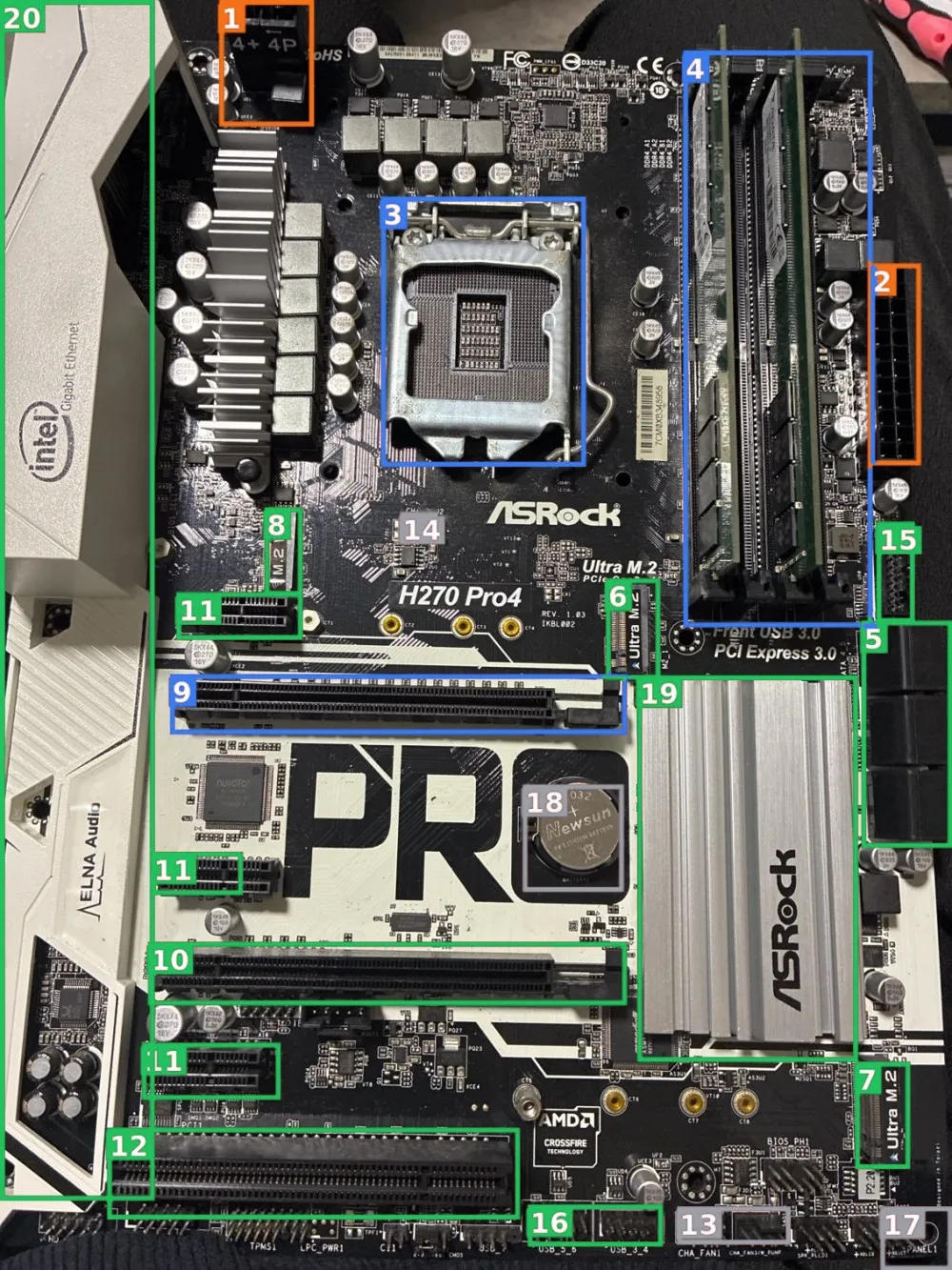
Roughly, the parts connect to the motherboard like this. Arrows show power, plain lines show data. The numbers on the boxes and arrows match the ones in the photo above.
The key point is that memory and the top PCIe x16 slot connect straight to the CPU, while SATA, M.2, USB and the rest talk to the CPU through the chipset (PCH).
The boxes in the photo above use the same colors as this diagram: orange for power, blue for direct to the CPU and green for through the chipset. Gray marks the things that don’t appear in the diagram (fan headers, the front panel header and the CMOS battery).
Power connectors
1. CPU auxiliary power (8 pin / 4+4 pin)
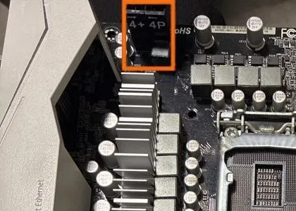
This connector takes 12V from the power supply for the CPU only. “4+4P” is printed on the board.
Power that comes in here goes through the VRM (the power circuit covered later), which steps the voltage down before it reaches the CPU.
2. Main power (ATX 24 pin)
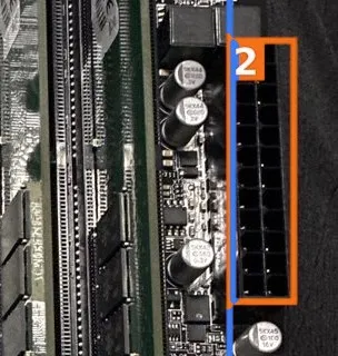
This is the main power connector from the power supply. It feeds the whole board: the chipset, memory, slots and so on.
The PC won’t start unless both 1 and 2 are plugged in.
CPU socket and memory slots
3. CPU socket (LGA1151)
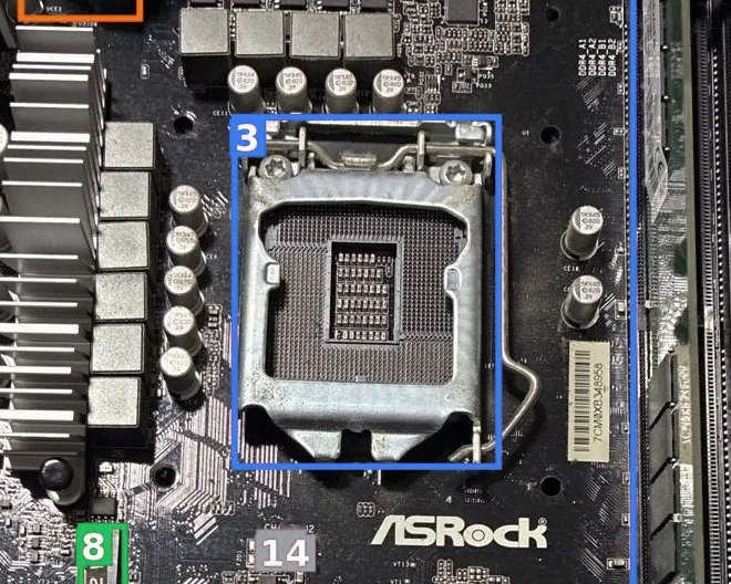
This is where the CPU sits. LGA means the pins are on the socket, and the CPU has flat contact pads.
The pins bend very easily, so it’s safest to keep the protective cover on whenever the CPU is out.
4. Memory slots (DDR4 × 4)
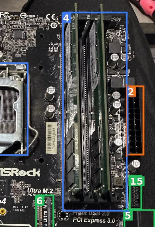
These slots take DDR4 memory. The board labels them “DDR4_A1 / A2 / B1 / B2”.
There are two channels, A and B. With two sticks, put one on the A side and one on the B side to run in dual channel. Check the manual for exactly which slots to use.
Storage connectors
5. SATA ports
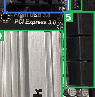
These connect HDDs, 2.5-inch SSDs and optical drives.
The SATA data cable plugs in here. The drive gets its power straight from the power supply through a SATA power cable.
6 and 7. Ultra M.2 slots
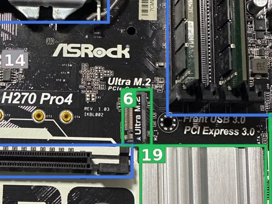
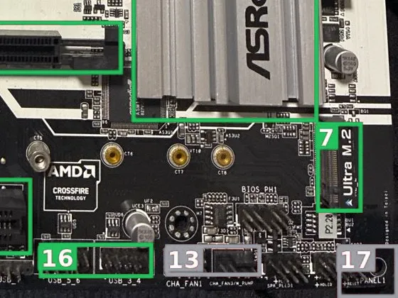
These take M.2 SSDs. Slot 6 is the upper one and slot 7 is at the bottom right. The board says “PCIe Gen3 x4”, so NVMe SSDs work here.
The SSD is held down with a screw at one of the gold standoff holes, chosen to match its length.
M.2 slots and SATA ports sometimes share bandwidth, so using an M.2 slot can disable some SATA ports. Check the manual for which combinations work.
Expansion slots
8. M.2 WiFi slot
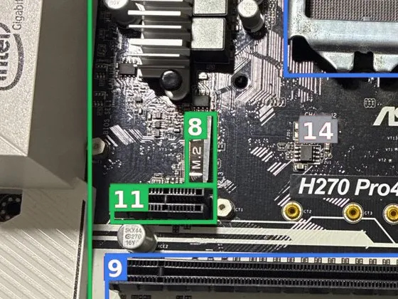
This M.2 slot is for a wireless LAN or Bluetooth module, not an SSD. The notch (key) is in a different place from the SSD slots.
9 and 10. PCI Express x16 slots
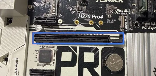
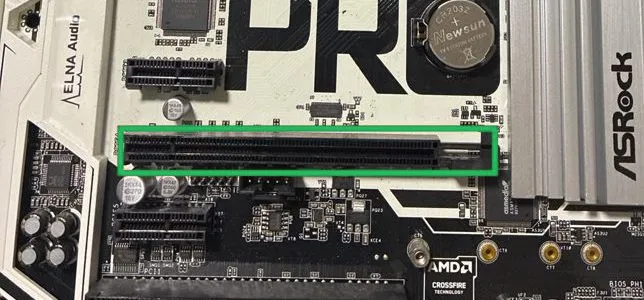
These are for graphics cards.
Slot 9, the upper one, is the main slot wired directly to the CPU, so that’s where the graphics card normally goes. Slot 10, the lower one, looks like x16, but according to the manual it runs at x4, so it has much less bandwidth.
11. PCI Express x1 slots
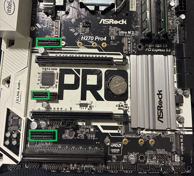
These short slots, three of them on this board, are for add-in cards such as LAN cards, sound cards and USB expansion cards.
12. PCI slot (legacy)
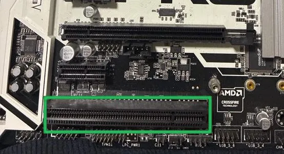
Labeled “PCI1” on the board, this is an older type of expansion slot for using old add-in cards.
Connectors for the case
13 and 14. Fan headers
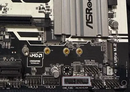
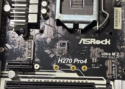
These 4 pin headers are for case fans. Number 13 is labeled “CHA_FAN1” and “CHA_FAN3/W_PUMP”, and the silkscreen at 14 reads “CHA_FAN2”.
One of the four pins carries the speed control signal (PWM), which the board uses to adjust fan speed to the temperature. “W_PUMP” means the header can also drive a water cooling pump.
15. USB 3.0 header (front)
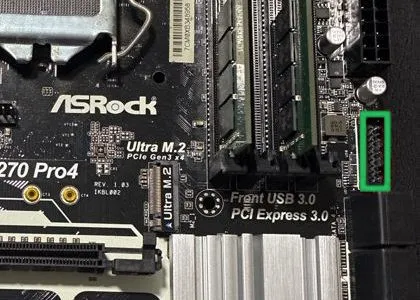
The cable from the USB 3.0 ports on the front of the case plugs in here.
16. USB 2.0 headers
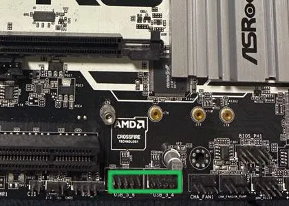
These 9 pin headers, labeled “USB_3_4” and “USB_5_6”, connect the front USB 2.0 ports, a card reader and similar.
17. Front panel header
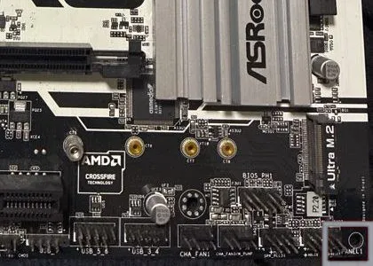
Labeled “PANEL1”, this header connects the case’s power button, reset button, power LED and drive activity LED.
The power button on the case only sends a “start up” signal to the board through this header. So if it comes loose, pressing the button does nothing.
Other parts on the board
18. CMOS battery
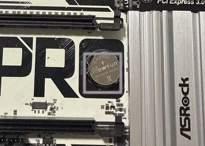
This coin battery (CR2032) keeps the BIOS settings and the clock while the PC is off.
If the clock starts drifting every time you boot, it’s time to replace it.
19. Chipset (H270) heatsink
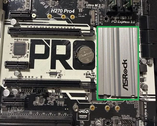
The chipset, an Intel H270, sits under the heatsink with the ASRock logo.
It gathers up SATA, M.2, USB, expansion slots and more, and relays them to the CPU.
20. Around the rear I/O panel
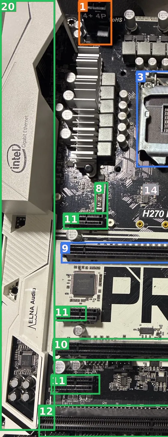
This is where the ports that stick out the back of the case are lined up: USB, LAN, video out, audio and so on.
The covers say “Intel Gigabit Ethernet” and “ELNA Audio”, and the LAN and audio circuits are in this area.
The power circuit around the CPU (VRM)
Next, some parts that aren’t connectors. I numbered them 21 to 24, to the left of and above the CPU socket. They’re all part of the power circuit, so their boxes use the same orange as power in the diagram.
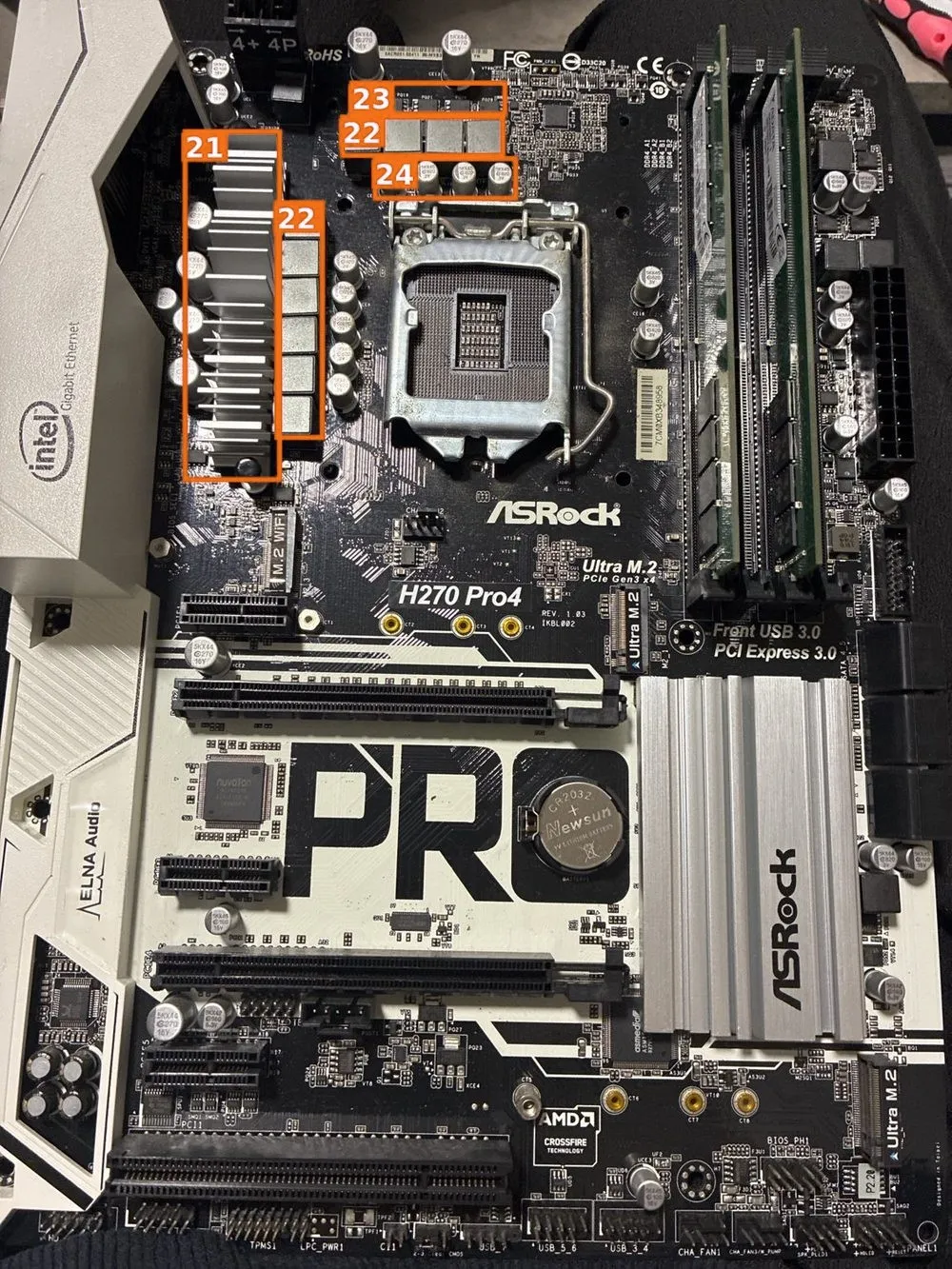
Around the CPU socket is the VRM, the power circuit that delivers steady power to the CPU.
Its job is to take the 12V from the power supply down to the roughly 1V the CPU runs on. These parts work together to do it.
21. Heatsink (for the VRM)
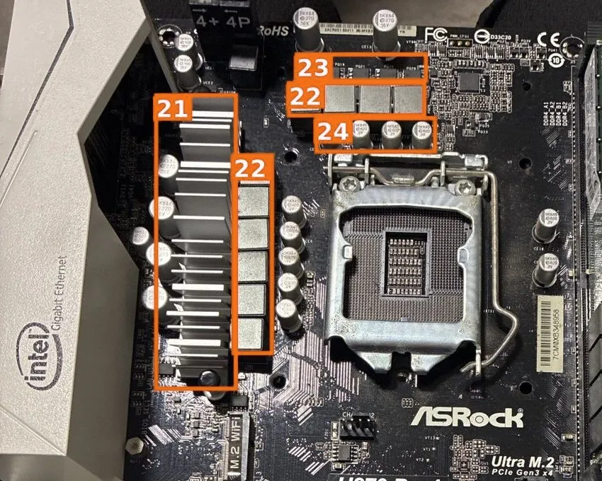
The VRM’s MOSFETs handle large currents and get hot. This metal plate carries the heat away.
A side note: a “heat spreader” is the metal lid on the CPU itself. Parts like this one on the motherboard are called heatsinks.
22. Chokes
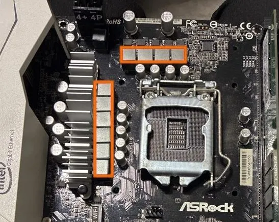
These gray square parts have coils inside that smooth out changes in current.
The MOSFETs switch on and off rapidly, which makes a choppy current. The chokes turn it into a smooth one.
23. MOSFETs
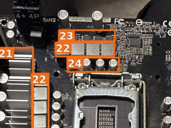
These semiconductors act as switches that turn the power on and off at high speed. Adjusting how long they stay on versus off is how the voltage gets stepped down.
Besides the spot in the photo, more MOSFETs sit under the heatsink at 21.
24. Capacitors
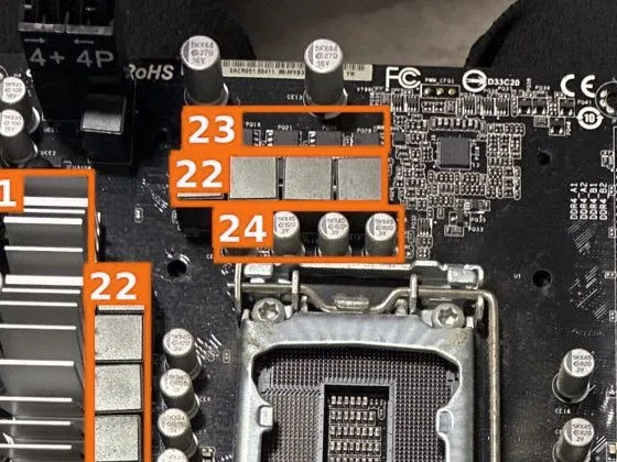
These cylindrical parts briefly store and release charge to keep the voltage from wobbling.
The top shows the capacitance (for example 820µF) and the voltage rating (for example 3V). They’re all over the board, but there are especially many around the CPU.
Wrapping up
Here is what plugs in where.
| Part | Where it connects |
|---|---|
| Power supply | 1 (CPU 4+4 pin), 2 (ATX 24 pin) |
| CPU | 3 (CPU socket) |
| Memory | 4 (DDR4 slots) |
| HDD, 2.5-inch SSD | 5 (SATA) |
| M.2 SSD | 6 and 7 (Ultra M.2) |
| Graphics card | 9 (PCIe x16) |
| Case fans | 13 and 14 (fan headers) |
| Front buttons and USB | 15, 16 and 17 |
Power goes through the VRM to the CPU. Data splits into what connects directly to the CPU (memory, graphics card) and what goes through the chipset (storage, USB and so on). That’s the basic layout of a motherboard.
All photos are of the actual board I took apart (ASRock H270 Pro4). For details such as slot bandwidth and which ports share lanes, check the manufacturer’s manual.
I’m not strong on low-level hardware and spend most of my time renting cloud machines, so as a learning exercise I plan to bring this PC back to life as a deploy target for the apps I’m going to build. It should give me a small taste of what the people running AWS and GCP actually do.
It’s full of dust, though, so it needs a good cleaning first, and I still need to check whether any parts have to be replaced. I might even head over to Akihabara, Tokyo’s electronics district, to look for some in person.
References
- H270 Pro4 (ASRock): slot and connector layout and specifications